RESISTOR-CAPACITOR
CIRCUIT
I. Introduction:
By this time, you are expected to be
familiar already with the different kinds of connections. To have a review,
there are three types which are series (e.g. Christmas lights), parallel
(lights in our homes) and network or the combination of series and parallel. Of
course, connections can be more complicated than network in which one of its
examples is RC circuit.
As a review, capacitor is a circuit
element that functions like a battery that can store electrical energy.
Resistor, on the other way around, is also a circuit element that functions as
regulator to current because of its known resistance. Combining the two and
there goes the type of circuit named as RC circuit.
II. Definition:
Resistor-Capacitor
circuit or also known as RC circuit is a type of connection wherein there are
capacitors and resistors as obviously it suggests to its name. This type of
circuit is used for filters and timing since this involves time delay.
III. Schematic Diagram:
 |
|
|
IV. Formulas:
The time delay depends on the circuit elements.
Therefore, this has built the relationship between resistance and capacitance
which is Resistance x Capacitance = Tau or τ. (RC=τ)
Time constant is defined as the time required to charge and discharge a
capacitor.
We have known already the process of charging and
discharging a capacitor since we have solely discussed it at the previous
chapter about capacitor. To give a review, when a switch is closed, current is
zero and the capacitor is charging. As the switch is opened, current will be
read since the capacitor is discharging. Below are the formulas involved in
charging and discharging a capacitor.
 |
| https://goo.gl/n6a1Pb |
V. Application:
Common applications of RC circuit are the following:
1. Series lights. The blinking of series lights during
Christmas involves timing.
 |
|
http://goo.gl/Bgf6BK
|
2. Pacemakers. Used to control the heartbeat for normal
beating.
 |
|
http://goo.gl/IN4HF4
|
3. Windshield wipers. Used to clear the glass when
travelling in rain.
 | |
| https://goo.gl/3b3ggj |
VI.
Laboratory Experiment
I.
Introduction:
RC circuit is a circuit comprises of resistor and
capacitor. The capacitor charges through the resistor and gets full depending
on its capacitance in a certain time called time constant. It will also
eventually discharges that can generate electricity for a period of time.
II. Objectives:
a. Set
up an RC circuit
b. Perform
the charging and discharging of a capacitor
c. Tabulate
the data using table for the charging and discharging
d. Graph
the data being tabulated.
III. Materials:
a. Power
supply
b. Capacitor
c. Resistor
d. Alligator
clips
e. Multitester
f. Stopwatch
II.
Procedures:
1. Determine the resistance of the
resistor.
2. Set-up the resistor and capacitor in
series.
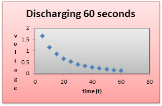
3. Charge the capacitor for one minute and
take the voltage for every 5 seconds interval.
4. Discharge the capacitor for one minute
and take again the voltage for every 5 seconds interval.
5. Record the data using table for
charging and discharging.
III.
Data
and Results:
TABLE
1: VOUT: 4.5 V, R1 = 5500 Ω, R2
= 180 Ω, C= 4700uF
t
(s)
|
VDROP
, Charging
|
VDROP,
Discharging
|
Current,
Charging
|
5
|
0.4 V
|
2.0 V
|
6.6 x 10⁻⁴ A
|
10
|
0.6 V
|
1.8 V
|
5.4 x 10⁻⁴ A
|
15
|
1.0 V
|
1.6 V
|
4.50 x 10⁻⁴ A
|
20
|
1.2 V
|
1.4 V
|
3.74 x 10⁻⁴ A
|
25
|
1.4 V
|
1.2 V
|
3.10 x 10⁻⁴ A
|
30
|
1.6 V
|
1.1 V
|
2.60 x 10⁻⁴ A
|
35
|
1.8 V
|
1.0 V
|
2.13 x 10⁻⁴ A
|
40
|
2.0 V
|
1.0 V
|
1.77 x 10⁻⁴ A
|
45
|
2.05 V
|
0.9 V
|
1.46 x 10⁻⁴ A
|
50
|
2.2 V
|
0.8 V
|
1.21 x 10⁻⁴ A
|
55
|
2.2 V
|
0.8 V
|
1.01 x 10⁻⁴ A
|
60
|
2.2 V
|
0.6 V
|
8.35
x
10-5 A
|
VI. Graphs:
Observation:
I observed that during charging,
the voltage reading is really increasing and the same for discharging in which it
was also decreasing. The charging was approximately 0.2-0.3 and during
discharging it was also discharging for about the same range.
Generalization:
The time used in
charging will be the time required to discharge it.
References:
Retrieved on September 6, 2015
from http://www.wisegeek.com/what-is-a-rc-circuit.htm
Retrieved on September 6, 2015
from http://www.electronics-tutorials.ws/rc/rc_1.html
Retrieved on September 6, 2015
from https://www.youtube.com/watch?v=OIpHPsnLlNU


Walang komento:
Mag-post ng isang Komento