 |
| https://goo.gl/7O2KGc |
CAPACITOR
I.
History
Capacitor comes
in many size, color and shape. In its history, the first famous type of
capacitor was named as Leyden jar. This Leyden jar could store electric charge
and could supply electricity. Capacitor is generally defined as any conductor
that is capable of storing charge.
 |
|
|
Water
Tank Analogy is commonly used to describe how capacitor works in a circuit. In
the process of charging, capacitor stores charges same with the water tank that
stores water. The amount of charges in the capacitor is also analogous to the
amount of water in the tank. In some point of time, it will stop storing when
it reached to its maximum capacity as the water tank also reached to its
maximum capacity of storing water. This
capacity of a capacitor is named as capacitance.
The position of the tank, which is placed in height, means that it requires
certain force to push water to be stored in it. For the part of the capacitor,
it also requires voltage for the charges to be stored in it. By the time we
need water, we will just open the valve and water will freely flow downward.
So, stored charges could also freely travel around the circuit producing
current even without connecting it to any voltage source. Hence, a capacitor
could supply current until it will be emptied and this process is called
discharging.
II.
Composition


III. Types
There is a very large variety
when we talk about types of capacitor
available in the market place and each one has its own set of characteristics
and applications, from very small capacitors up to large power metal-can type
capacitors which are used for high voltage power. The comparison between the
different types of capacitor is
generally based on the type of dielectric used between its plates. Just like
resistors, there are also variable types of capacitors which allow us to vary
their capacitance value in our desire. Same with resistors, capacitors also
have fixed and variable or adjustable capacitors.
The following are some types of
capacitors.

- Electrolytic
Capacitors

https://goo.gl/GRVxWJ Electrolytic Capacitors are preferably to used when large values of capacitance are to be connected. One of its electrodes is somewhat like jelly or paste made with semi-liquid electrolyte solution. However, a very thin layer of oxide is used as dielectrics.Most of the electrolytic types of capacitors have polarity, polarity means positive terminal of a voltage source must be connected with positive terminal of the capacitor also. Hence if the polarity is not observed, then the capacitor will be damaged.Hence, all polarized electrolytic capacitors have their polarity clearly marked with a negative sign to indicate the negative terminal and this polarity must be followed.Electrolytic are most preferred capacitors due to their low cost and small size but in the other side, they could easily be damaged like over-voltage, reversed polarity and over temperature.Electrolytic Capacitor comes in two basic forms, the Aluminum and Tantalum Electrolytic Capacitors.a. Aluminum Electrolytic Capacitors
https://goo.gl/MNH8cP
These are capacitors that composed of two rolled aluminum foil with absorbent paper between them all sealed in a can. These are large capacitors are designed to have greater value of capacitance making it to be their advantage among the other type.b. Tantalum Capacitors
This type of capacitor is made tantalum pentoxide. Although Tantalum Capacitors are polarized, still they can tolerate more than Aluminum if connected in reverse. Their main advantages over Aluminum are their size in which they are smaller, lighter and more stable. But sad to say, they have lower capacitance storage hence making it to have lower working voltage also.
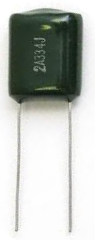
- Ceramic CapacitorsCeramic Capacitors or generally called as Disc Capacitors, are made by coating two sides of a small porcelain or ceramic disc with silver and are then stacked together to make a capacitor.These are composed of titanium acid barium as its dielectric. Together with electrolytic, they are also commonly used. They are made with high capacitance values ranging from 1pF to 220pF and can work up to 50V. Common main advantages of using these are they are constructed in coils resulting to have low inductance and they are very suited for high frequency application.3. Film CapacitorsAvailable film capacitors in the market usually have capacitance ranges from 5pF to 100 uF but this would depend on the composition and voltage rating. Same with the other types, film capacitors are varied in shapes and sizes. Yet, this type has also its sub-types (enumerated below) because of varied properties of dielectric.a. Polyester capacitors which are composed of metal plates with polyester film between them or metalized film deposited as insulator. They come in 1nF to 15nF with working voltages from 50V to 1500V.
http://goo.gl/dT b. Polypropylene capacitors are made with polypropylene film dielectric and have high working voltage up to 3000V. This makes it useful in circuits operating voltages that are typically high.
http://goo.gl/dT c. Polystyrene capacitors having dielectrics made of polystyrene and coming in low values usually 10pF to 47nF. They are commonly made with 5% to 10% tolerance. Their working voltages range from 30V to 630V but they are not suitable for high-frequency signals because of its coil inside construction. Another disadvantage is their capacitance value is affected with temperature.


 |
| http://goo.gl/dT |
d.
Polycarbonate
capacitors are capacitors having polycarbonate dielectric. Their capacitance
comes in range of 100pF up to 10µF and could work up to 400V in DC. They are
commendable if fairly good temperature so they don’t vary as temperature
changes. They are not suited for high-precision applications since they have
fairly high tolerance levels from 5% to 10%.
 |
| http://goo.gl/dT |
4. Dielectric Capacitors
 |
|
|
These are usually the variable type where
can be adjusted into variation of capacitance that is required. Variable
dielectric capacitors are multi-plate-air-spaced types that have a set of fixed
plates and a set of movable plates which move in between the fixed plates.
Hence, the position or the distance of the movable plates with respect to the
fixed plates determines the final capacitance value.
As
well as the continuously variable types, preset type variable capacitors are
also available called Trimmers. These are generally small devices that
can be adjusted or “pre-set” to a particular capacitance value with the aid of
a small screwdriver and are available in very small capacitance’s of 500pF or
less and are non-polarized.
IV.
The
process of Charging and Discharging
As a capacitor is being connected to a voltage source specifically a
DC source, it undergoes two processes namely “charging” and “discharging” in
specific conditions.
Figure below shows a charging process of a capacitor. In the circuit, the capacitor (C)
is connected to a voltage source (V) and current (i) flows though the circuit.
One plate will hold negative charges and the other one will hold positive
charges in equal amount or number. Once the voltage of the terminals of the
capacitor is already equal to the voltage source, the current will stop to flow
and that ends the charging phase.

When we disconnect the voltage source
(V) from the circuit, the capacitor (C) will discharge through the resistor (RD)
and current (i) will flow and will stop as the capacitor gets emptied or the
voltage of the plates drop to zero. Thus, discharging phase also ends.
 |
The resistances (RD and RC)
can affect the charging and discharging rate of the capacitor. Hence, a
relationship is built between Resistance (R) and Capacitance (C) in which their
product is called the Time Constant τ.
The capacity of a capacitor to hold charges is called capacitance and has a unit of Farad.
V.
Formulas
Time
Constant
|
τ
= RC
|
Capacitance
equivalent in series
|
 |
Capacitance
equivalent in parallel
|
 |
IV.
Laboratory
Experiment
VOUT:
4.5 V, R1 = 5500 Ω , R2 = 180 Ω, C= 4700uF
t (s)
|
VDROP , Charging
|
VDROP, Discharging
|
Current, Charging
|
5
|
0.4 V
|
2.0 V
|
6.6 x 10⁻⁴ A
|
10
|
0.6 V
|
1.8 V
|
5.4 x 10⁻⁴ A
|
15
|
1.0 V
|
1.6 V
|
4.50 x 10⁻⁴ A
|
20
|
1.2 V
|
1.4 V
|
3.74 x 10⁻⁴ A
|
25
|
1.4 V
|
1.2 V
|
3.10 x 10⁻⁴ A
|
30
|
1.6 V
|
1.1 V
|
2.60 x 10⁻⁴ A
|
35
|
1.8 V
|
1.0 V
|
2.13 x 10⁻⁴ A
|
40
|
2.0 V
|
1.0 V
|
1.77 x 10⁻⁴ A
|
45
|
2.05 V
|
0.9 V
|
1.46 x 10⁻⁴ A
|
50
|
2.2 V
|
0.8 V
|
1.21 x 10⁻⁴ A
|
55
|
2.2 V
|
0.8 V
|
1.01 x 10⁻⁴ A
|
60
|
2.2 V
|
0.6 V
|
8.35x 10⁻⁵ A
|
Graphical
Representation:

Walang komento:
Mag-post ng isang Komento